
For high performance sailing yachts and power boats, I’d recommend using ball links in all link joints. Ball links are commonly used by the RC airplane and helicopter community and also in RC car and buggy. They are back lash free and give superior control in critical applications. This is my preferred method as I used them in my many helicopters.
For modest performing scale boats and casual RC boats in general, a bent up piece of piano wire will do the job just fine.
Below is an illustration showing a typical RC boat rudder linkage. It is best to make sure the servo arm and rudder arm are parallel at neutral position.
Also note the “V” bend – its a great feature allowing you to bend the linkage outside the assembly and tweak the length by adjusting the angles of the “V” once its all mounted in the model.
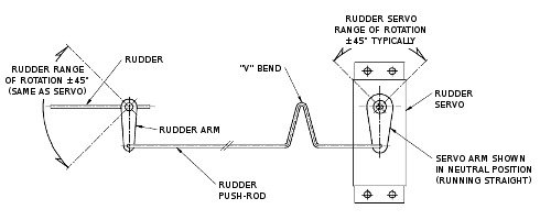
This illustration shows an RC boat rudder sweep angle of +/-45 degrees. This is the most convenient, since the arms on the rudder and servo are the same length.
It is also said by many modellers that this is the “correct” way to make a servo linkage as the rod will stay parallel with a common center-line through the two pivot points. As a result, the rudder angle is split exactly down the middle (+/-45 degrees).
This is just a basic guide to rudder linkage, and I would recommend further research as to which is the best type for your model boat.


